Axpert-Eazy Mini Series VFD
General Purpose Advanced User-Friendly VFD
Amtech continuously invests in R&D to remain ahead in technology. The Axpert-Eazy Mini Series VFD is designed for the low-power segment while delivering high performance, protection and energy efficiency.
The drive is easy to configure, control and monitor. It is highly reliable and resilient to harsh industrial conditions. It includes powerful software functions such as built-in PLC, PID control, multi-pump control, pattern run, application macros and many advanced diagnostics features.
Range: 1 – 10 HP (0.75 – 7.5 kW)
Voltage: 380 – 480 V, 3-Phase, 50/60 Hz

.svg)
- Latest 7th Generation IGBT
- Fully configurable digital and analog I/Os
- Digital Operation Panel made of Graphical LCD with white back light LED (optional)
- Two graph screens with selectable graph signal and resolution (for Graphical DOP)
- Plastic enclosure
- IP21 / NEMA 1 protection
- Compact design – downsized VFD series requiring less installation space
- In-built PLC with functional block based programming range of fully configurable I/O
- 1 fixed digital input dedicated for Safe Torque Off (STO) function
- Digital output programmable for STO feedback
- 32 configurable serial parameters to read 24 parameters and write 8 parameters simultaneously
- PID, Multi-pump, Ring Spinning Frame, and Pattern Run software functions
- IE2 compliant VFD
- Built-in PID, PLC & application specific software reduces peripheral costs
- Built-in energy saving calculator with high-efficiency operation mode
- Multi-pump control function
- Auxiliary drive control function
- 128×64 graphical LCD display with white back light (optional)
- 9-key keypad with real-time clock (optional)
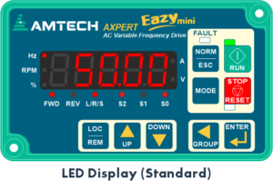
- Standard 7-segment LED display with 9-key keypad
- Self-explanatory full parameter names in English (optional)
- Auto rotation of normal screens with settable time
- Diagnosis functions to help pinpoint faults
- Fault history storing last 20 faults with timestamp and 8 operational parameters
- Peak load monitoring with timestamp and other parameters

| Power Rating | Mains Supply Voltage | -4: 380–480 VAC (Nominal 415 VAC), 3-Phase, 3-Wire, -15% / +10% |
| Mains Supply Frequency | 50 Hz, 60 Hz or 50/60 Hz (±3 Hz) | |
| Input Current | Indicated in table | |
| Output Current |
Nominal output current available continuously (No overload allowed) 120% for 60 sec, 140% for 2.5 sec every 5 minutes – Normal Duty (ND) 150% for 60 sec, 175% for 2.5 sec every 5 minutes – Heavy Duty (HD) |
|
| Control Functions | Control Method | Digital Space Vector PWM Control |
| Control Mode | V/F Open Loop, Vector Control Open Loop | |
| Frequency Range | 0.10 – 599.00 Hz (V/F Control) | |
| Frequency Accuracy | Digital: ±0.01% (0–50°C) / Analog: ±0.01% (0–50°C) | |
| Output Frequency Resolution | 0.0001 Hz (20-bit) | |
| Frequency Setting Resolution | 0.01 Hz Digital, 0.012 Hz / 50 Hz Analog (12-bit) | |
| V/Hz Characteristics | 2 Pre-programmed patterns + 1 Custom 3-point setting pattern | |
| Torque Boost | Manual / Automatic selectable: 0–20% | |
| Acceleration / Deceleration Time | 0.1 – 600,000 seconds | |
| Linear or S-Curve selectable | ||
| Skip Frequency | Three selectable frequencies, band up to 10 Hz | |
| Slip Compensation | Up to 5 Hz | |
| Carrier Frequency | Default 5 kHz, Adjustable 1–10 kHz | |
| Operation Specifications | Speed Search Function | Allows drive to start with rotating motor without damage or tripping |
| Kinetic Energy Buffering | Drive runs using load kinetic energy during power fluctuation and resumes normal speed when power returns | |
| Power Loss Carry Through | Up to 5 seconds smooth operation during power loss without output torque | |
| DC Braking | Start Frequency: 0.1–50 Hz, Time: 0–25 sec, Brake Current: 15–150% | |
| Dynamic Braking Circuit | In-built | |
| Dynamic Braking Resistor | External (Optional) | |
| Frequency / Torque Setting Input |
Keypad (Digital Operation Panel) Analog Input: 2 kΩ Potentiometer / Programmable Analog Inputs Digital Input: Frequency Increase/Decrease, Preset Speeds Serial Communication: RS-485 Built-in PLC Analog Outputs |
|
| Auto Restart | Up to 10 attempts with selectable fault types | |
| PID Controller | Built-in PID controller usable as standalone with configurable process units | |
| Display | LED Display & Keypad | 5-digit 7-segment LED display with unit indicators, motor direction, status LEDs (Run, Stop, Fault) and 9-key keypad |
| Graphical Display (Optional) | 128×64 Graphical LCD with white backlight, real-time clock, selectable monitoring parameters, graph screens, load analyzer and auto screen rotation | |
| Protective Specifications | Protective Functions | Overcurrent, Drive Overload, Motor Overload, DC Bus Over/Under Voltage, Temperature Fault, Phase Loss, Earth Fault, External Fault, Communication Loss, Speed Deviation, Overspeed and many others |
| Smooth Operation | Current Limit, Speed Search, Auto Restart, Power Loss Carry Through, Kinetic Energy Buffering and IGBT temperature protection | |
| Diagnosis Functions | Diagnosis Mode, Load Analyzer, Peak Monitoring, Maintenance Timers, Debug Mode for logic verification | |
| Fault History | Stores last 20 faults with timestamp and operational parameters (Output Frequency, Current, DC Bus Voltage, IGBT Temp, Power etc.) | |
| Environment | Installation Location | Indoor |
| Vibration | EN 60068-2-6, Acceleration: 1g, Frequency: 10–150 Hz | |
| Ambient Temperature | -10°C to 50°C (14°F – 122°F) | |
| Storage Temperature | -10°C to 70°C (14°F – 158°F) | |
| Altitude | Up to 1000 m without derating, above this 5% derating per 305 m | |
| Humidity | 0–95% non-condensing | |
| Enclosure | IP20 | |
| Reference Standards | UL 508C, UL 61800-5-1, CSA C22.2 No.247-17, IEC 61800-5-1, CE (EN 50178, EN 61800-3, EN 61800-5-1, EN 61800-5-2) | |
- If the default carrier frequency is exceeded, derate the output current by 5% per 1 kHz as the reduced
- The input power factor is considered approximately 6 and motor efficiency 85% for the input current calculation. The inverter efficiency is >98%. The input power factor is approximately 0.9 when input choke of 3% rating is used.
- The output current indicates the total effective value including the higher
- The HP shown is maximum applicable motor output for a 4-pole standard induction
| Input Voltage 441…480 V | ||||||||
| Model AMT-EM |
Frame | Input Current | Output Rating | |||||
| No Overload Rating | Normal Duty Rating | Heavy Duty Rating | ||||||
| A | A | HP | A | HP | A | HP | ||
| -02A6-4 | P3 | 1.9 | 2.5 | 1 | 2.4 | 1 | 2.4 | 0.75 |
| -03A3-4 | P3 | 2.8 | 3.2 | 1.5 | 3 | 1.5 | 2.5 | 1 |
| -004A-4 | P3 | 3.8 | 3.8 | 2 | 3.6 | 2 | 3.2 | 1.5 |
| -05A8-4 | P3 | 5.6 | 5.5 | 3 | 5.2 | 3 | 4.5 | 2 |
| -008A-4 | P3 | 7.6 | 7.6 | 4 | 7 | 4 | 5.5 | 3 |
| -010A-4 | P3 | 10.1 | 9.5 | 5 | 9 | 6 | 7.6 | 4 |
| -014A-4 | P3 | 14 | 13 | 7.5 | 12 | 7.5 | 10.5 | 5 |
| -018A-4 | P3 | 19 | 17 | 10 | 16 | 10 | 13 | 7.5 |

| Frame | Fig | Dimensions in inch (mm) | ||||||||
| A | B | C | D | E | F | G | H | J | ||
| P3 | 1 | 8.34 (212) | 5.70 (145) | 6.85 (174) | 5.08 (129) | 7.87 (200) | 0.21 (5.5) | 0.17 (4.5) | 0.84 (21.5) | 1.24 (31.5) |

- Precise, Accurate & Stable Speed Control
- Flexibility of Operations
- Reduced Machine Setup Time
- Improved End Product Quality
- Improved Productivity
- Improvement in Power Factor
- Energy Saving
- Reduced Hardware
- Ease of Operations
Axpert-Eazy mini Series Variable Frequency Drive is a modern Digital Signal Processor based high performance VFD and is easy to use. It employs new generation IGBT as a switching device and pwm control techniques to apply commanded output to control the motor speed. It's applications includes:
Application Specific Features:
- Conveyor
- Centrifuge
- Fermentor
- Pump
- Compressor
- Fan
- Crane / Hoist
- Pump Jack (Artificial Lift)
Your VFD Motor Controller is Always In-Stock
Contact Amtech Drives to get the right VFD solution for your application.
Contact Us For Details