


Overview
Specification
Model & Rating
Dimension & Weight
Install & Wiring
Applications
Download
Features:
- Latest 7th Generation IGBT
- Fully configurable digital and analog I/Os
- Digital Operation Panel made of Graphical LCD with white back light LED (optional)
- Two graph screens with selectable graph signal and resolution (for Graphical DOP)
- Plastic enclosure
- IP 21 / NEMA 1 protection
- Compact - The New Series VFD is downsized considerably and requires less space to install.
- In-built PLC with Functional Block Based Programming Range of Fully Configurable I/O
- 1 fixed digital inputs dedicated for Safe Torque Off (STO) function, the digital output can be programmed for the STO feedback
- 32 Configurable Serial Parameters helps to read 24 parameters and write 8 parameters in a one go respectively
- PID, Multi-pump, Ring Spinning Frame, Pattern Run software functions
- IE2 Compliant VFD
- Built-in PID, PLC & application specific software reduces the peripherals’ cost.
- Built-in Energy Saving Calculator High-Efficiency operation mode
- Multi-pump control function
- Auxiliary Drive control function
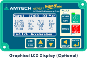
- 128x64 Graphical LCD Display with white back light (optional)
- 9-key keypad with Real Time Clock (optional)
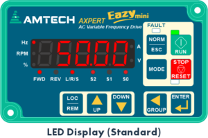
- Standard 7-segment LED display with 9-key keypad
- Self-explanatory full parameter name in English (optional)
- Auto Rotation of Norm Screens with settable time
- Diagnosis Functions help to pin point the fault
- Fault history, last 20 faults with time stamp and 8 important operational parameters
- Peak Load monitoring with time stamp and other parameters
| Power Rating | Mains supply voltage | -4: 380…480 VAC (nominal voltage 415 VAC), 3-Phase, 3-Wire, -15%, +10% |
| Mains supply frequency | 50 Hz, 60 Hz or 50/60 Hz, +/- 3 Hz | |
| Input current | Indicated in table | |
| Output current | Nominal output current available continuously, No overload allowed 120% for 60 seconds, 140% for 2.5 seconds every 5 minutes, Normal Duty (ND) use 150% for 60 seconds, 175% for 2.5 seconds every 5 minutes, Heavy Duty (HD) use |
|
| Control Functions | Control Method | Digital Space Vector PWM Control |
| Control Mode | V/F Open Loop, Vector Control Open Loop | |
| Frequency Range | 0.10…599.00 Hz for V/F Control | |
| Frequency Accuracy | Digital references: ±0.01% (0...50 °C) / Analog References: ±0.01% (0...50 °C) | |
| Output Frequency Resolution | 0.0001 Hz (20-bit) | |
| Frequency Setting Resolution | 0.01 Hz Digital, 0.012 Hz/ 50 Hz Analog (12-bit) | |
| V/ Hz Characteristics | 2-Preprogrammed patterns, 1-Custom 3-point setting pattern | |
| Torque Boost | Manual / Automatic Selective: 0…20% | |
| Acceleration/ Deceleration Time | 0.1…600,000 Seconds | |
| Linear or S-Curve selective | ||
| Skip Frequency | Three frequencies can be set, band can be set up to 10.0 Hz | |
| Slip Compensation | Slip compensation frequency up to 5.0 Hz | |
| Carrier Frequency 1) | Default: 5 kHz, 1……10kHz Settable | |
| Operation Specifications | Speed Search Function | Allows the drive to start with rotating machine without damage / tripping. |
| Kinetic Energy Buffering | In case of momentary power fluctuations allows the drive to run using the kinetic energy of the load, accelerates to the set speed when power resumes | |
| Power Loss Carry Through | Up to 5 seconds for smooth operation of system during power loss with no output torque | |
| DC Braking | DC Braking start frequency 0.1…50.0 Hz, Time: 0…25 seconds, Brake current: 15…150% | |
| Dynamic Braking Circuit | In-built | |
| Dynamic Braking Resistor | External (Optional) | |
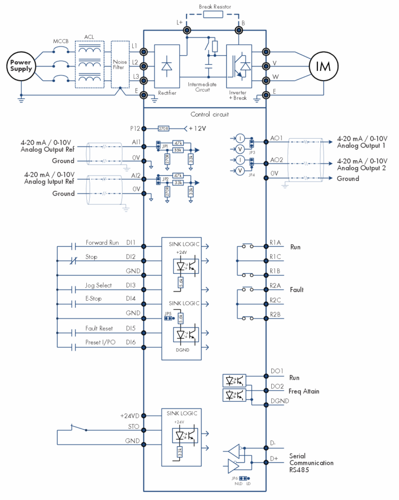
| Frequency / Torque Setting Input | Digital Operation Panel (Keypad) Analog Input: 2 kΩ Potentiometer, Programmable Analog Inputs Digital Input: Static Pot (Frequency Increase/ Frequency Decrease), Preset Speeds (Preset input0, 1 & 2) Serial: RS-485 Built-in PLC: PLC Analog output1 & 2 | |
| Auto Restart | Adjustable up to 10 times, selectable for different faults | |
| PID Controller | Inbuilt PID controller can be used as stand alone. PID signals can be and assigned with actual process parameter units. | |
| I/O Specifications | Analog Inputs | 2 Analog Programmable Inputs with settable Gain, Bias, Minimum and Maximum scaling AI1 & AI2: 0…10 Vdc / 4…20 mA |
| Digital Inputs | 6 Digital Inputs, Sink (NPN) / Source (PNP) and Active Close / Active Open selectable | |
| Programmable options: Not Used, Jog Select, Ramp Select, Preset I/P0, Preset I/P1, Preset I/P2, Freq Increase, Freq Decrease, Aux Drive, Emergency Stop, Fault Reset, External fault1, External fault2, Reverse, Terminal, Ref Select0, Ref Select1, PR Step Skip, PR Step Hold, PR/RSF Reset, PID Bypass, PID Disable, Run, Stop, Drive Enable, PLC input1, PLC input2, PLC input3, PLC input4, PLC input5, PLC input6, Torque mode, Ready1 F/B, Forward Run, Reverse Run, Forward Jog, Reverse Jog and MBRK Answer, Motor PTC | ||
| Safety Inputs | 1 Digital Input for Safe Torque Off (STO), +24V Sink logic | |
| Digital outputs | 2 Digital Outputs, open collector type and Active Close / Active Open selectable | |
| Programmable options: Not Used, Local, Run, Forward Run, Reverse, Reverse Run, I-Detection1, I- Detection2, Freq Attain, Speed Detect1, Speed Detect2, Acceleration, Deceleration, Aux Drive, Timer Output, Zero Speed, Fault Alarm, PID Up Limit, PID Lo Limit, Temp Alarm, Ready, Ready1, Pump1, Pump2, Pump3, Pump4, Doff-End Alarm, Sleep Mode, Fault, PLC O/P1, PLC O/P2, PLC O/P3, PLC O/P4, PID F/B Upper Limit, PID F/B Lower Limit, Fan Control, MBRK1, MBRK2, MBRK3, KEB ON, Overload fault, Overcurrent fault, Earth fault, Over temperature fault, Overvoltage fault, STO, On Time1, On Time2 and On Time3. | ||
| Potential Free Contacts | 2 Relays, 1-NO, 1-NC for 5 A @ 240 VAC | |
| Programmable options same as digital outputs | ||
| Programmable Analog Outputs | 2 Analog Outputs with settable Gain, Bias, Minimum and Maximum scaling AO1 & AO2: 0…10 Vdc / 4…20 mA | |
| Programmable options: Output frequency, Motor output current, Output power, Output voltage, DC bus voltage, PID output, IGBT temperature, PLC AO1, PLC AO2, Unipolar torque current, Excitation current, Set frequency, Bipolar torque current, Motor OL ,Drive OL, Drive output current, Test 0% and Test 100%. | ||
| Network connectivity | RS-485 for PC Interface with Modbus-RTU protocol connectivity as standard | |
| Display | Seven segment LED Display and Keypad unit | Digital Operation Panel 5 digit seven segment LED display with 2 decimal points, Unit indication, Motor direction , Start control and Drive’s status LEDs display, 9-Key Keypad, 3-Status indicating LED for Run, Stop, Fault. 12 predefined normal parameter display |
| Graphical Display and Keypad unit (Optional) | Digital Operation Panel 128x64 Graphical LCD with white back light LED, 9-Key Keypad, 3-Status indicating LED for Run, Stop, Fault | Real Time Clock Simultaneous display of 8 selectable monitor parameters Two graph screens with selectable graph signal and resolution Load Analyzer screens | Auto rotation of screens with settable time interval | |
| Protective Specifications | Protective Function | Overcurrent fault, Drive overload fault, Motor overload fault, DBR overload fault, Undercurrent fault, DC Bus Overvoltage fault, DC Bus Undervoltage fault, Temperature fault, Input & Output phase loss fault, Earth (Ground) fault, External fault, Charging fault, Current sensor fault, EEPROM fault, 4…20mA Reference missing fault, Auto tuning fault, Emergency stop, Communication loss, Output unbalance current fault, Speed deviation fault, Overspeed fault, Motor overtemperature fault, IGBT Driver fault, Watchdog fault, Control Power fail fault etc. |
| Smooth Operation | Current Limit, Speed Search, Auto Restart (with individual fault selection), Power Loss Carry Through (PLCT), Kinetic energy buffering (KEB) and IGBT overtemperature alarm functions | |
| Diagnosis Functions | Helps in pinpointing the fault. Diagnosis Mode, Load Analyzer1, Load Analyzer2, Peak Monitoring, Number of Power On, Overtemperature fault, Overvoltage fault, Overcurrent fault, Earth fault, Overload fault, Auto restart monitoring; 3 warning timer for maintenance; Debug Mode for logic verification | |
| Fault history | Last 20 faults with date & time, status and 8 operational parameters (Output frequency, Output current, DC bus voltage, IGBT temperature, Output Power, Total power ON time, kWH, MWH) | |
| Environment | Installation location | Indoor |
| Vibration | As per EN 60068-2-6, Acceleration: 1g, Frequency: 10…150 Hz | |
| Ambient temperature | 14…122°F (-10…50°C) | |
| Storage temperature | 14…158°F (-10…70°C) | |
| Altitude (above sea level) | 3300 ft (1000 m) without derating, above this derate 5% per 1000 ft (305 m) | |
| Humidity | 0…95% maximum non-condensing | |
| Enclosure | IP20 | |
| Reference Standards | UL 508C, UL 61800-5-1, CSA C22.2 NO. 247-17, IEC 61800-5-1, CE (EN 50178:1997, EN 61800-3:2004+a1:2012, EN 61800-5-1:2007), EN 61800-5- 2:2007 | |
- If the default carrier frequency is exceeded, derate the output current by 5% per 1 kHz as the reduced
- The input power factor is considered approximately 6 and motor efficiency 85% for the input current calculation. The inverter efficiency is >98%. The input power factor is approximately 0.9 when input choke of 3% rating is used.
- The output current indicates the total effective value including the higher
- The HP shown is maximum applicable motor output for a 4-pole standard induction
| Input Voltage 441…480 V | ||||||||
| Model AMT-EM |
Frame | Input Current | Output Rating | |||||
| No Overload Rating | Normal Duty Rating | Heavy Duty Rating | ||||||
| A | A | HP | A | HP | A | HP | ||
| -02A6-4 | S1/P3 | 1.9 | 2.5 | 1 | 2.4 | 1 | 2.4 | 0.75 |
| -03A3-4 | S1/P3 | 2.8 | 3.2 | 1.5 | 3 | 1.5 | 2.5 | 1 |
| -004A-4 | S1/P3 | 3.8 | 3.8 | 2 | 3.6 | 2 | 3.2 | 1.5 |
| -05A8-4 | S1/P3 | 5.6 | 5.5 | 3 | 5.2 | 3 | 4.5 | 2 |
| -008A-4 | P3 | 7.6 | 7.6 | 4 | 7 | 4 | 5.5 | 3 |
| -010A-4 | P3 | 10.1 | 9.5 | 5 | 9 | 6 | 7.6 | 4 |
| -014A-4 | P3 | 14 | 13 | 7.5 | 12 | 7.5 | 10.5 | 5 |
| -018A-4 | P3 | 19 | 17 | 10 | 16 | 10 | 13 | 7.5 |


| Frame | Fig | Dimensions in inch (mm) | ||||||||
| A | B | C | D | E | F | G | H | J | ||
| S1 | 1 | 8.27 (210) | 5.27 (134) | 6.10 (155) | 3.94 (100) | 7.78 (197.5) | 0.33 (8.5) | 0.33 (8.5) | 0.59 (15) | 2.28 (58) |
| P3 | 2 | 8.34 (212) | 5.70 (145) | 6.85 (174) | 5.08 (129) | 7.87 (200) | 0.21 (5.5) | 0.17 (4.5) | 0.84 (21.5) | 1.24 (31.5) |
Axpert-Eazy mini Series Variable Frequency Drive is a modern Digital Signal Processor based high performance VFD and is easy to use. It employs new generation IGBT as a switching device and pwm control techniques to apply commanded output to control the motor speed. It's applications includes:
Application Specific Features:
- Conveyor
- Centrifuge
- Fermentor
- Pump
- Compressor
- Fan
- Crane/Hoist
- Pump Jack (Artificial Lift)