


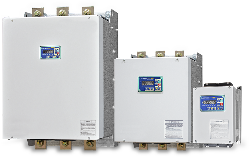
Overview
Specification
Models & Rating
Dimension & Weight
Install & Wiring
Application
Download
Features:
- Energy efficient design - Cooling from control as per heat-sink temperature. This will increase fan life and also reduce the power consumption
- Conformal coated circuit boards (PCB) as standard
- Provision for in-built motor PTC for motor over temperature protection
- Internal Bypass up to AMT-OT-iB/eB-0360A
- Energy Meter Standard, displayed in both kWH & MWH
- Wide range class 2 to 30 electronic overload
- Kick Voltage Start / Jog Function
- Fully Configurable Analog and Digital Inputs / Outputs
- 32-Character, 2-Line LCD Display with Backlit and 8-key Keypad
- In-line (3 - wire) / Inside Delta (6 - wire) operating modes
Advantages:
- Reduces starting power surge
- Limits disruption of power system
- Eliminates mechanical starting shock
- Extends motor life
- Allows for more start/stop per hour
- Replaces elector-mechanical starters
- No moving parts that requires maintenance
- Eliminates need for special dual wound motors
Monitoring:
- Three phase current
- Three phase voltage
- Line frequency
- Power factor
- Conduction time & run time
- Fault History
| Control | Control system | Digital 32-bit Digital Signal Controller | |||||
| Serial port | Supports RS-485 Modbus as standard, Profibus-DP (slave), DeviceNet, CANopen, Ethernet, ControlNet are optional. | ||||||
| Operation Specifications | Current feedback & Electronic OLR | Motor current: Adjustable up to 30 % of Unit Current Rating | |||||
| I-Low Level: 0…100% of full load motor current | |||||||
| I-Low Time: 0…20 minutes | |||||||
| I-Trip Level: 100…800% of full load motor current | |||||||
| I-Limit Level: 100…600% of full load motor current | |||||||
| I-Limit Time: 10…60 seconds | |||||||
| Selected Class 2 to Class 30 overload | |||||||
| Digital Inputs | 4-Programmable Sequence Inputs, Sink / Source changeable, max 5 mA each | ||||||
| Programmable between 17 different options: Not Used, Terminal, Jogging, External Fault, Fault Reset, Bypass Contactor, Main Contactor, E-Stop, Ramp Hold, Reverse Contactor, Run, Stop, Motor PTC, PLC I/P 1…4 | |||||||
| Potential Free Contacts | 3-Programmable relays: | 1-Relay | 1-NO for 5 A @ 240 VAC | ||||
| 2-Relays | 1-NO, 1-NC for 5 A @ 240 VAC | ||||||
| Programmable between 41 different options: Not Used, Ready, Run, Top of Ramp, Fault Alarm, I-Limit Alarm, Low Current Alarm, High Current Alarm, Temp Alarm, Reverse Contactor, Main Contactor, External Fan Control, Over Current Fault, Under Current Fault, I-Unbalance Fault, Overload Fault, Over Voltage Fault, Mains Off Fault, Phase Loss Fault, External Fault, Emergency Fault, Motor PTC Short Fault, Motor PTC Over Temperature, Power Not OK, Bypass Relay Fault, Eeprom Fault, Ground Fault, Phase Direction Fault, Over Freq Fault, Under Freq Fault, Thermistor OT Fault, Thermistor NC Fault, Thermostat Fault, Firing Fault, Thermistor Short Fault, SCR Short Fault, Watchdog Fault, PLC O/P 1…3 | |||||||
| Programmable Current Outputs | 2-Programmable analog current outputs IO: 4...20 mA, 12-bit | ||||||
| Programmable between 7 different options: Output Current, Active Power, Reactive Power, Power factor, Motor torque, Heat sink temperature, Motor PTC, PLC Analog output 1 and 2 | |||||||
| Motor PTC Feedback | One or three Motor PTC can be connected for motor over temperature protection | ||||||
| Operation Specifications | Start Mode | V-Ramp Start | Dual Ramp Selection | Kick Time: 0...2.0 sec | |||
| V-Ramp Up Time1: 1...240 sec | Kick Voltage: 0...90% | ||||||
| Pedestal-1: 25...90% | Target: 25...100% | ||||||
| I-Ramp Start | I-Ramp Up Time: 1...60 sec | I-Proportional Gain: 0.01...2.00 | |||||
| Initial Current: 100...300% | I-Integral Time: 0.01...100.00 | ||||||
| T-Ramp Start | T-Ramp Up Time: 1...240 sec | T-Proportional Gain: 0.1...2.0 | |||||
| Initial Torque: 1...250% | T-Integral Time: 0.01...100.00 | ||||||
| Torque Limit: 1...250% | |||||||
| Stop Mode | V-Ramp Stop | V-Ramp Down Time: 1...240 sec | |||||
| Initial Voltage: 100...25% | Final voltage: 70...25% | ||||||
| Brake Stop | Brake Ramp Time: 0.1...20.0 sec | ||||||
| Brake Voltage: 25...100% | Brake Time: 1...240 sec | ||||||
| T-Ramp stop | T- Ramp Down Time: 1...240 sec | End Torque: 1...100% | |||||
| Coast to stop | |||||||
| Control Mode | Local (Digital Operation Panel) | ||||||
| Terminal | |||||||
| Serial | |||||||
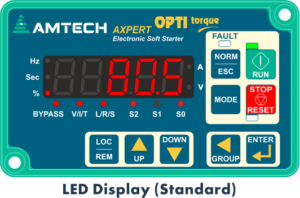
| Display | Display and Keypad module (Standard) | Digital Operation Panel 5 digit seven segment LED display with 2 decimal points, Unit indication, Start Mode, Start control, Bypass and Starter’s status LEDs display, 9-Key Keypad, 3-LED for Run, Stop, Fault. 13 predefined normal parameter display. Can be mounted on panel door with optional extension cable. Can be mounted on panel door with optional extension cable | |||||
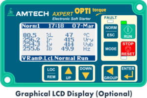
| Graphical Display and Keypad unit (Optional) | Digital Operation Panel 128x64 Graphical LCD with white back light LED, 9-Key Keypad, 3-Status indicating LED for Run, Stop, Fault, Real Time Clock Simultaneous display of 8 selectable monitor parameters Two graph screens with selectable graph signal and resolution Auto rotation of screens with settable time interval. Can be mounted on panel door with optional extension cable | ||||||
| Start Duty | Overload | Ten equally spaced starts per hour at 350% current, each of 30 seconds duration, i.e. 30 seconds on time and 330 second off time. (For models 720 to 1065 A, 6 equal start). | |||||
| Protection | Transient Protection | RC Snubber across thyristor | |||||
| MOV across input power supply | |||||||
| Last 20 faults with status and 8 operational parameters like Input voltage (Vry & Vyb), Output current (%), Active Power (kW), Energy Meter (kWH & MWH), Power On Time (Hrs) and Heat sink temperature (oC) | |||||||
| Over current fault | Temperature fault | Reverse contactor fault | |||||
| Over load fault | Phase direction fault | SCR Short fault | |||||
| Ground fault | I-Unbalance fault | Main contactor fault | |||||
| Phase Loss fault | Firing fault | Bypass contactor fault | |||||
| Over voltage fault | Over frequency fault | Mains off fault | |||||
| Motor PTC fault | Under frequency fault | ||||||
| Environment | Installation Location | Indoor | |||||
| Ambient Temperature | 5...122 °F (-15...50 °C) | ||||||
| Storage Temperature | -4...158 °F (-20...70 °C) | ||||||
| Altitude (above sea level) | 1000 m (3300 ft) without derating, above this derate 3% per 305 m (1000 ft) up to 4000 m (13200 ft) | ||||||
| Humidity | 0…95% max non condensing | ||||||
| Enclosure | IP20 up to AMT-iB-0110A-4-X model, other models have IP00 (other can be provided on demand) | ||||||
| Reference Standards | UL 508, UL 60947-4-2, CSA C22.2 60947-4-2, IEC 60947-4-2, IEC 60947-1, CE (EN 60947-4-2), IEC 60529 | ||||||
| Note: | |||||||
| 1: Contact Amtech for Inside Delta option up to 360 A in AMT-OT-iB series above 480V input. | |||||||
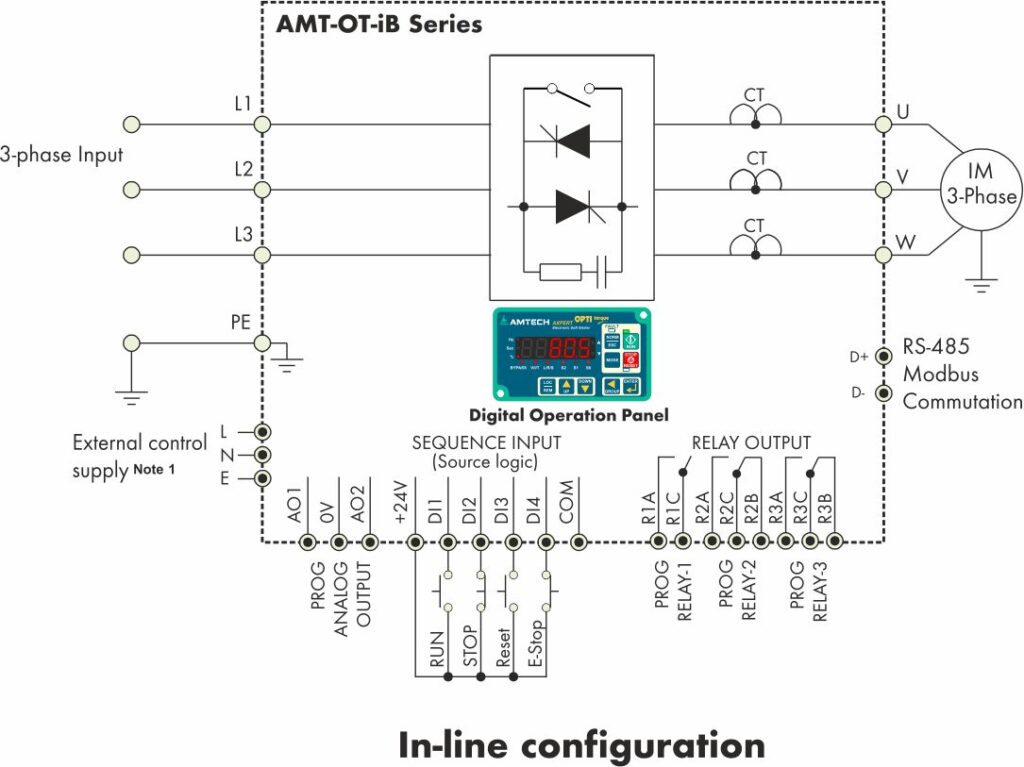
Applicable Motor current and kW defined for In-line configuration Model number: AMT-OT-iB/eB-XXXXA-4/6-X-X
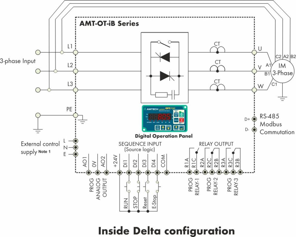
Applicable Motor current and kW defined for Inside Delta configuration Model number: AMT-OT-iB/eB-XXXXA-4/6-X-X
| Model | Standard Duty Application (350% for 30 Sec) | Severe Duty Application (500% for 30 Sec) | ||||||||||||||
| Motor Current (A) | 208V | 240V | 415V | 460V | 500V | 575V | 690V | Motor Current (A) | 208V | 240V | 415V | 460V | 500V | 575V | 690V | |
| HP | HP | kW | HP | kW | HP | kW | HP | HP | kW | HP | kW | HP | kW | |||
| -0015A | 15 | 5 | 5 | 5.5 | 10 | 11 | 15 | 15 | 11 | 3 | 3 | 3.7 | 7.5 | 10 | 10 | 11 |
| -0023A | 23 | 7.5 | 7.5 | 7.5 | 15 | 15 | 20 | 18.5 | 15 | 5 | 5 | 5 | 10 | 15 | 15 | 15 |
| -0028A | 28 | 10 | 10 | 11 | 20 | 18.5 | 25 | 22 | 20 | 7.5 | 7.5 | 7.5 | 15 | 20 | 20 | 18.5 |
| -0034A | 34 | 10 | 15 | 15 | 25 | 22 | 30 | 30 | 23 | 7.5 | 7.5 | 7.5 | 15 | 20 | 20 | 18.5 |
| -0044A | 44 | 15 | 15 | 18.5 | 30 | 30 | 40 | 37 | 28 | 10 | 10 | 11 | 20 | 25 | 25 | 22 |
| -0052A | 52 | 15 | 20 | 22 | 40 | 37 | 50 | 45 | 34 | 10 | 15 | 15 | 25 | 30 | 30 | 30 |
| -0065A | 65 | 20 | 25 | 30 | 50 | 37 | 60 | 55 | 44 | 15 | 15 | 18.5 | 30 | 40 | 40 | 37 |
| -0078A | 78 | 25 | 30 | 37 | 60 | 45 | 75 | 75 | 52 | 15 | 20 | 22 | 40 | 50 | 50 | 45 |
| -0087A | 87 | 30 | 30 | 45 | 75 | 55 | 100 | 90 | 60 | 20 | 25 | 30 | 50 | 50 | 60 | 55 |
| -0096A | 96 | 30 | 40 | 55 | 75 | 55 | 100 | 90 | 65 | 20 | 25 | 30 | 50 | 50 | 60 | 55 |
| -0110A | 110 | 40 | 40 | 55 | 100 | 75 | 125 | 110 | 78 | 25 | 30 | 37 | 60 | 60 | 75 | 75 |
| -0125A | 125 | 40 | 50 | 55 | 100 | 75 | 125 | 110 | 87 | 30 | 30 | 45 | 75 | 75 | 100 | 90 |
| -0160A | 160 | 50 | 60 | 75 | 125 | 90 | 150 | 132 | 110 | 40 | 40 | 55 | 75 | 100 | 100 | 110 |
| -0180A | 180 | 60 | 75 | 90 | 150 | 110 | 175 | 160 | 125 | 40 | 50 | 55 | 100 | 100 | 125 | 110 |
| -0215A | 215 | 75 | 75 | 110 | 175 | 132 | 215 | 200 | 160 | 50 | 60 | 75 | 125 | 125 | 150 | 132 |
| -0250A | 250 | 100 | 100 | 132 | 200 | 160 | 250 | 250 | 180 | 60 | 75 | 90 | 150 | 150 | 175 | 160 |
| -0320A | 320 | 100 | 125 | 160 | 250 | 200 | 300 | 315 | 215 | 75 | 75 | 110 | 175 | 175 | 215 | 200 |
| -0360A | 360 | 125 | 150 | 200 | 300 | 250 | 350 | 355 | 250 | 100 | 100 | 132 | 200 | 215 | 250 | 250 |
| -0414A | 414 | 150 | 175 | 220 | 350 | 250 | 450 | 400 | 290 | 100 | 125 | 160 | 250 | 275 | 300 | 250 |
| -0477A | 477 | 200 | 200 | 250 | 400 | 315 | 500 | 450 | 320 | 100 | 125 | 160 | 250 | 275 | 300 | 315 |
| -0515A | 515 | 200 | 250 | 250 | 450 | 355 | 535 | 500 | 360 | 125 | 150 | 200 | 300 | 355 | 350 | 355 |
| -0600A | 600 | 200 | 250 | 315 | 500 | 400 | 600 | 585 | 414 | 150 | 200 | 220 | 350 | 355 | 450 | 400 |
| -0720A | 720 | 250 | 300 | 400 | 600 | 500 | 700 | 630 | 477 | 200 | 250 | 250 | 400 | 425 | 500 | 450 |
| -0832A | 832 | 300 | 350 | 450 | 700 | 560 | 800 | 710 | 515 | 200 | 250 | 250 | 450 | 475 | 535 | 500 |
| -0900A | 900 | 350 | 375 | 500 | 750 | 630 | 900 | 800 | 600 | 200 | 275 | 315 | 500 | 535 | 600 | 585 |
| -0960A | 960 | 350 | 400 | 585 | 800 | 680 | 960 | 900 | 672 | 250 | 300 | 355 | 600 | 600 | 650 | 585 |
| -1065A | 1065 | 400 | 450 | 630 | 900 | 750 | 1000 | 1000 | 720 | 250 | 300 | 400 | 600 | 750 | 700 | 630 |
| Model | Standard Duty Application (350% for 30 Sec) | Severe Duty Application (500% for 30 Sec) | ||||||||||||||
| Motor Current (A) | 208V | 240V | 415V | 460V | 500V | 575V | 690V | Motor Current (A) | 208V | 240V | 415V | 460V | 500V | 575V | 690V | |
| HP | HP | kW | HP | kW | HP | kW | HP | HP | kW | HP | kW | HP | kW | |||
| -0015A | 25 | 7.5 | 7.5 | 7.5 | 15 | 15 | 20 | 18.5 | 19 | 5 | 5 | 5.5 | 10 | 11 | 15 | 15 |
| -0023A | 40 | 10 | 15 | 15 | 25 | 22 | 30 | 30 | 25 | 7.5 | 7.5 | 7.5 | 15 | 15 | 20 | 18.5 |
| -0028A | 48 | 15 | 15 | 18.5 | 30 | 30 | 40 | 37 | 34 | 10 | 15 | 15 | 25 | 22 | 30 | 30 |
| -0034A | 58 | 15 | 20 | 22 | 40 | 37 | 50 | 45 | 39 | 10 | 15 | 15 | 25 | 22 | 30 | 30 |
| -0044A | 76 | 25 | 30 | 37 | 60 | 45 | 75 | 75 | 48 | 15 | 15 | 18.5 | 30 | 30 | 40 | 37 |
| -0052A | 89 | 30 | 30 | 45 | 75 | 55 | 100 | 90 | 58 | 15 | 20 | 22 | 40 | 37 | 50 | 45 |
| -0065A | 112 | 40 | 40 | 55 | 100 | 75 | 125 | 110 | 76 | 25 | 30 | 37 | 60 | 45 | 75 | 75 |
| -0078A | 134 | 40 | 50 | 55 | 100 | 75 | 125 | 110 | 89 | 30 | 30 | 45 | 75 | 55 | 100 | 90 |
| -0087A | 150 | 50 | 60 | 75 | 125 | 90 | 150 | 132 | 103 | 30 | 40 | 55 | 75 | 55 | 100 | 90 |
| -0096A | 166 | 50 | 60 | 75 | 125 | 90 | 150 | 132 | 112 | 40 | 40 | 55 | 100 | 75 | 125 | 110 |
| -0110A | 190 | 60 | 75 | 90 | 150 | 110 | 175 | 160 | 134 | 40 | 50 | 55 | 100 | 75 | 125 | 110 |
| -0125A | 216 | 75 | 75 | 110 | 175 | 132 | 215 | 200 | 150 | 50 | 60 | 75 | 125 | 90 | 150 | 132 |
| -0160A | 276 | 100 | 100 | 132 | 200 | 160 | 250 | 250 | 190 | 60 | 75 | 90 | 150 | 110 | 175 | 160 |
| -0180A | 311 | 100 | 125 | 160 | 250 | 200 | 300 | 315 | 216 | 75 | 75 | 110 | 175 | 132 | 215 | 200 |
| -0215A | 371 | 125 | 150 | 200 | 300 | 250 | 350 | 355 | 276 | 100 | 100 | 132 | 200 | 160 | 250 | 250 |
| -0250A | 432 | 150 | 175 | 220 | 350 | 250 | 450 | 400 | 311 | 100 | 125 | 160 | 250 | 200 | 300 | 315 |
| -0320A | 553 | 200 | 250 | 250 | 450 | 355 | 535 | 500 | 371 | 125 | 150 | 200 | 300 | 250 | 350 | 355 |
| -0360A | 622 | 200 | 250 | 315 | 500 | 400 | 600 | 585 | 432 | 150 | 175 | 220 | 350 | 250 | 450 | 400 |
| -0414A | 716 | 250 | 300 | 400 | 600 | 500 | 700 | 630 | 501 | 200 | 200 | 250 | 400 | 315 | 500 | 450 |
| -0477A | 825 | 300 | 350 | 450 | 700 | 560 | 800 | 710 | 553 | 200 | 250 | 250 | 450 | 355 | 535 | 500 |
| -0515A | 890 | 350 | 375 | 500 | 750 | 630 | 900 | 800 | 622 | 200 | 250 | 315 | 500 | 400 | 600 | 585 |
| -0600A | 1038 | 350 | 400 | 585 | 800 | 680 | 960 | 900 | 716 | 250 | 300 | 400 | 600 | 500 | 700 | 630 |
| -0720A | 1245 | 420 | 500 | 710 | 1000 | 850 | 1200 | 1100 | 825 | 300 | 350 | 450 | 700 | 560 | 800 | 710 |
| -0832A | 1439 | 500 | 600 | 800 | 1200 | 1000 | 1500 | 1400 | 890 | 350 | 375 | 500 | 750 | 630 | 900 | 800 |
| -0900A | 1557 | 550 | 630 | 850 | 1280 | 1050 | 1400 | 1500 | 1038 | 350 | 400 | 585 | 800 | 680 | 960 | 900 |
| -0960A | 1660 | 600 | 700 | 900 | 1340 | 1150 | 1550 | 1600 | 1162 | 400 | 450 | 630 | 900 | 750 | 1100 | 1000 |
| -1065A | 1842 | 700 | 800 | 1000 | 1500 | 1250 | 1800 | 1700 | 1245 | 420 | 500 | 710 | 1000 | 850 | 1200 | 1100 |
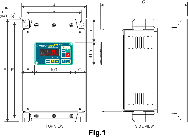
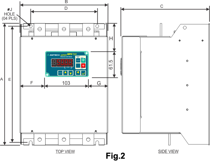
| Model | Dimensions in mm (inch) | Weight in kg (lb) | ||||||||
| A | B | C | D | E | F | G | H | J | ||
| AMT-OT-iB-0015A, -0023A, -0028A, -0034A, -0044A, -0052A, -0065A, -0078A, -0087A, -0096A, -0110A | ||||||||||
| Fig.1 | 273 (10.75) | 173 (6.81) | 230 (9.05) | 148 (5.83) | 255 (10.04) | 35 (1.38) | 35 (1.38) | 61.5 (2.42) | 7 (0.28) | 6.7 (14.8) |
| AMT-OT-iB-0125A, -0160A, -0180A, -0215A | ||||||||||
| Fig.2 | 393 (15.47) | 308 (12.13) | 274.5 (10.81) | 233 (9.17) | 373 (14.69) | 102 (4.02) | 102 (4.02) | 111 (4.37) | 11 (0.43) | 19 (41.9) |
| AMT-OT-iB-0250A, -0320A, -0360A | ||||||||||
| Fig.2 | 425 (16.73) | 308 (12.13) | 310.5 (12.22) | 233 (9.17) | 405 (15.94) | 102 (4.02) | 102 (4.02) | 120 (4.72) | 11 (0.43) | 23 (50.7) |
| AMT-OT-eB-0015A, -0023A, -0028A, -0034A, -0044A, -0052A, -0065A, -0078A, -0087A, -0096A, -0110A, -0125A | ||||||||||
| Fig.2 | 273 (10.75) | 173 (6.81) | 230 (9.05) | 148 (5.83) | 255 (10.04) | 35 (1.38) | 35 (1.38) | 61.5 (2.42) | 7 (0.28) | 6.7 (14.8) |
| AMT-OT-eB-0160A, -0180A, -0215A | ||||||||||
| Fig.2 | 380 (14.96) | 213 (9.09) | 267 (10.5) | 138 (5.43) | 359 (14.13) | 54.5 (2.15) | 54.5 (2.15) | 97 (3.82) | 11 (0.43) | 14.5 (32.0) |
| AMT-OT-eB-0250A, -0320A, -0360A | ||||||||||
| Fig.2 | 425 (16.73) | 308 (12.13) | 285.5 (11.24) | 233 (9.17) | 405 (15.94) | 102 (4.02) | 102 (4.02) | 102 (4.72) | 11 (0.43) | 23 (50.7) |
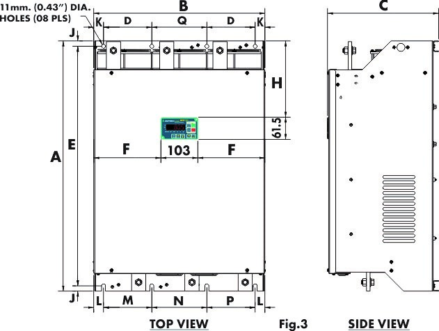
| Model | Weight in kg (lb) | ||||||||||||||
| A | B | C | D | E | F | H | J | K | L | M | N | P | Q | ||
| AMT-OT-iB-0414A, -0477A, -0515A, -0600A | |||||||||||||||
| Fig.3 | 705 (27.7) | 482 (19.0) | 312.5 (12.3) | 136 (5.3) | 675 (26.5) | 189.5 (7.4) | 214 (8.4) | 15 (0.6) | 25 (1.0) | 25 (1.0) | 136 (5.3) | 155 (6.1) | 136 (5.3) | 155 (6.1) | 67 (147.7) |
| AMT-OT-iB-0720A, -0832A, -0900A, -0960A, -1065A | |||||||||||||||
| Fig.3 | 830 (32.7) | 578 (22.7) | 358.5 (14.1) | 173 (6.8) | 800 (31.5) | 237.5 (9.3) | 316 (12.4) | 15 (0.6) | 25 (1.0) | 25 (1.0) | 173 (6.8) | 177 (7.0) | 173 (6.8) | 177 (7.0) | 112 (246.9) |
| AMT-OT-eB-0414A, -0477A, -0515A, -0600A | |||||||||||||||
| Fig.3 | 520 (20.5) | 482 (19.0) | 318 (12.5) | 136 (5.3) | 490 (19.3) | 189.5 (7.5) | 171 (6.7) | 15 (0.6) | 27.5 (1.08) | 27.5 (1.08) | 136 (5.3) | 155 (6.1) | 136 (5.3) | 155 (6.1) | 50 (110.2) |
| AMT-OT-eB-0720A, -0832A, -0900A, -0960A, -1065A | |||||||||||||||
| Fig.3 | 616 (24.3) | 578 (22.8) | 358 (14.1) | 173 (6.8) | 800 (31.5) | 585 (23.1) | 214 (8.4) | 15 (0.6) | 27.5 (1.08) | 27.5 (1.08) | 173 (6.8) | 177 (7.0) | 173 (6.8) | 177 (7.0) | 86 (189.5) |
Note: 1. Control supply 1-phase, 50/60 Hz, 90...270 VAC or 115/230 VAC to be provided by customer. Refer ordering code.
From industrial machinery to energy management, Soft Starters play a pivotal role in enhancing performance and reliability
Applications includes:
- Conveyer
- Pump
- Blower
- Wire Drawer
- Rolling Mill
- Air Handling Unit
- Textile Equipment
- Machine Tool
- Crusher
- Mixer
- Saw
- Agitator